Driver for Wireless Sensors Integrated into Real-timeControl Applications
(the VMonDrv module)
User guide
2020-09-03
Plzeň (Pilsen), Czech Republic
Contents
1.1 Introduction
1.2 System requirements
1.3 Installation of the driver on the host computer
1.4 Installation of the driver on the target device
1.4.1 Windows machines
1.4.2 Linux machines
2 Including the driver in the project
2.1 Adding the VMonDrv driver
2.2 Connecting the inputs and outputs in the control algorithm
2.3 Input ports of the V-Mon 4000
3 Driver configuration
4 Driver sensing nodes and network configuration
5 Troubleshooting
Chapter 1
The VMonDrv driver and the REXYGEN system
1.1 Introduction
This manual describes the VMonDrv driver for working with wireless sensing platform V-Mon 4000 [1] within the REXYGEN system. Internal accelerometer, analogue inputs and sensed sequences information are provided on all operating systems. The driver may also provide the status information about temperature, battery voltage and external power supply. The driver was developed by the REX Controls company.
1.2 System requirements
The VMonDrv driver can be used on Windows and Linux target devices. The USB version requires a free USB port while Ethernet version (supported only on Linux) requires Ethernet port.
In order to use the driver, the host computer (development) and the target computer (runtime) must have the following software installed:
|
Host computer |
|
|
Operating system |
one of the following: Windows 7/8/10 |
|
REXYGEN system |
version for Windows operating system |
|
Target device |
|
|
REXYGEN system |
runtime core for the corresponding operating system |
|
IO driver |
version for the corresponding operating system |
|
|
|
|
|
|
1.3 Installation of the driver on the host computer
The VMonDrv driver is included in the installation package of the Development tools of the
REXYGEN system. It is necessary to select the corresponding package in the installer. The
REXYGEN system typically installs to the
C:\Program Files\REX Controls\REX_<version> folder.
The following files are copied to the installation folder:
- bin\VMonDrv_H.dll – Configuration part of the VMonDrv driver.
- DOC\ENGLISH\VMonDrv_ENG.pdf – This user manual.
1.4 Installation of the driver on the target device
1.4.1 Windows machines
The target part of the driver, which is used for running REXYGEN on Windows 7/8/10 is included in the Development tools of the REXYGEN system as mentioned above. The following file has to be present in the installation folder:
- bin\VMonDrv_T.dll – Target part of the VMonDrv driver which is called by the RexCore runtime module.
1.4.2 Linux machines
If there is no RexCore runtime module installed on your target device, install it first using the Getting started guide of the REXYGEN system [2].
In order to connect the sensing node V-Mon 4000 into the REXYGEN system the driver
must be installed. This is done from command line using the command:
Debian:
sudo apt-get install rex-vmonrvt
Chapter 2
Including the driver in the project
The driver is included in the project as soon as the driver is added to the project main file and the inputs are connected in the control algorithms.
2.1 Adding the VMonDrv driver
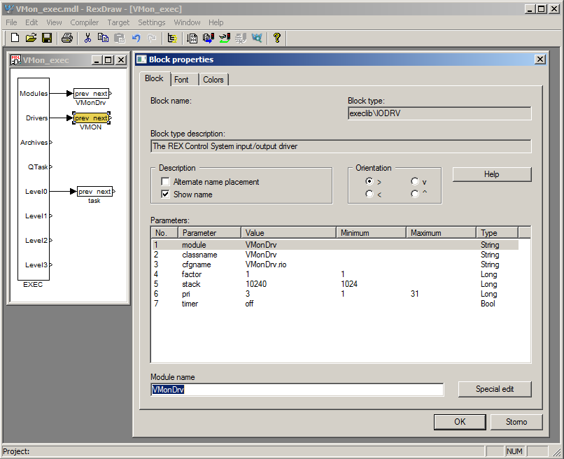
The project main file with the VMonDrv driver included is shown in Figure 2.1.
There are 2 blocks which must be added to the project to include the driver. First the MODULE block is attached the the Modules output of the EXEC function block. It must be renamed to VMonDrv.
The other block of type IODRV is named VMON and it is connected to the Drivers output of the main EXEC block. The three most important parameters are:
- module – name of the module linked to the driver, in this case VMonDrv – the name is CASE SENSITIVE!
- classname – class of the driver, in this case VMonDrv – the name is CASE SENSITIVE!
- cfgname – name of the driver configuration file (*.rio, REXYGEN Input/Output), which is discussed in chapter 3
The name of this block (VMON, see Fig. 2.1), is the prefix of all input and output signals provided by this driver.
The above mentioned parameters of the IODRV function block are configured in REXYGEN Studio program. The configuration dialog is shown also in Fig. 2.1.
2.2 Connecting the inputs and outputs in the control algorithm
The inputs and outputs of the driver must be interconnected with the individual tasks (.mdl files). The individual tasks (QTASK or TASK blocks) are connected to the QTask, Level0,…, Level3 outputs of the main EXEC block.
2.3 Input ports of the V-Mon 4000
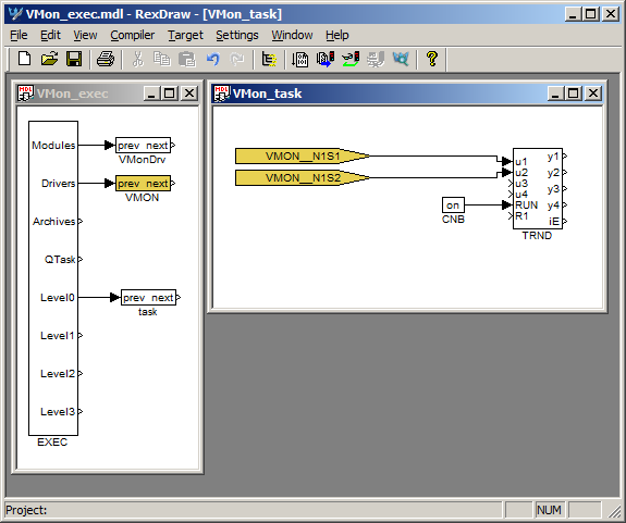
The inputs and of the VMonDrv driver can be accessed as shown in Fig. 2.2.
One block of the From type allowing the user to read one input has the Goto tag set to VMON__N1S1, while the other has this tag set to VMON__N1S2. The number in the flag following the N letter corresponds with the node identification number (ID) - where to find node ID is described in the chapter 3 and the S letter is followed by the signal number. For some of the signals, there is a possibility to use an alias. Complete list of the signals and aliases may be found in the table 2.1. The blocks always have the VMON prefix right at the beginning of the tag followed by two _ characters (underscore).
| Signal number | Function | Alias |
| S1 | Analogue input 1 | – |
| S2 | Analogue input 2 | – |
| S3 | Analogue input 3 | – |
| S4 | Analogue input 4 | – |
| S6 | Accelerometer x | ax |
| S7 | Accelerometer y | ay |
| S8 | Accelerometer z | az |
| S10 | Compass x | cx |
| S11 | Compass y | cy |
| S12 | Compass z | cz |
| S14 | Gyroscope x | gx |
| S15 | Gyroscope y | gy |
| S16 | Gyroscope z | gz |
| S18 | Battery | bat |
| S19 | Temperature | temp |
| S20 | External power supply | extI |
| S22 | Time delay between last two samples | tDelay |
| S23 | Time stamp of the last sample | tsLast |
| S24 | Last sequence number | seqNo |
The connection string in the From flag thus consist of the driver name , two underscores __, (N) letter and node identification number, (S) letter and signal number (or alias).
For the signals may be separated into groups (analogue inputs, accelerometer, status) there is a possibility to use multi-input blocks (INQUAD). The advantages of such blocks are increased processing speed and better readability of the algorithm. The signal numbers and corresponding aliases are listed in the table 2.2. Detailed description of the multiple-input blocks may be found in the function block reference manual[3].
| Signal number | Function | Alias |
| S5 | All analogue inputs | S |
| S9 | Accelerometer signals | A |
| S13 | Compass signals | C |
| S17 | Gyroscope signals | G |
| S21 | Status information | stat |
All supported input blocks are listed in the example in the installation folder
\EXAMPLES\IODRV\VMON_Example
Status information (signals S18 - S21) are available only when using a version for Windows in combination with the Boost library (configuration number 4 in the chapter 3).
Chapter 3
Driver configuration
The driver configuration is saved in a *.rio file, defined in the corresponding IODRV block as described in section 2. The *.rio file is simple text file, thereby is editable in any text editor. The basic structure is following:
Config 4
ComName "COM6"
Node {
NodeID 1
SignalCount 4
}
Node {
NodeID 4
SignalCount 2
}
}
The rows have this meaning:
- VMonDrv – Defines a section for VMonDrvconfiguration
- Config – Identification number of configuration from table 3.1
- ComName – Communication port name, all possibilities are in table 3.1
- Node – Defines a section for sensing node configuration
- NodeID – Node ID. May be found in the node serial number or using Intertia Studio
- SignalCount – Active analogue inputs count
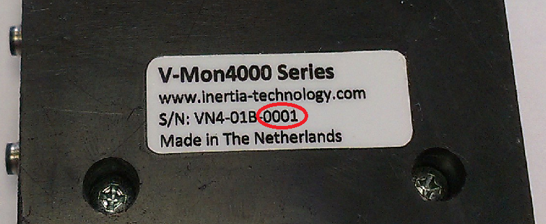
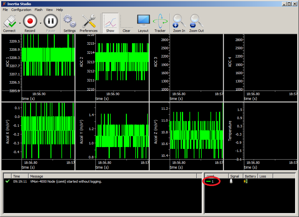
Node identification number may be found on the device label, the last four digits are the unique ID (fig. 3.1). Another option is to use the Inertia Studio software, the node ID is shown in the bottom right corner along with status information (see fig. 4.1).
For the example above, the first analogue input from the node with ID has in the From flag VMON__N1S1. The first analogue input from the node with ID is read from the flag VMON__N4S1.
| Configuration | Function | Communication ports |
| [x stands for port number] | ||
| 1 | OS Linux, Ethernet communication | "edevx" or "ethx" |
| 2 | OS Linux, USB communication | "/dev/ttyACMx" |
| 3 | OS Windows | "COMx" |
| 4 | OS Windows the Boost library | "COMx" |
Chapter 4
Driver sensing nodes and network configuration
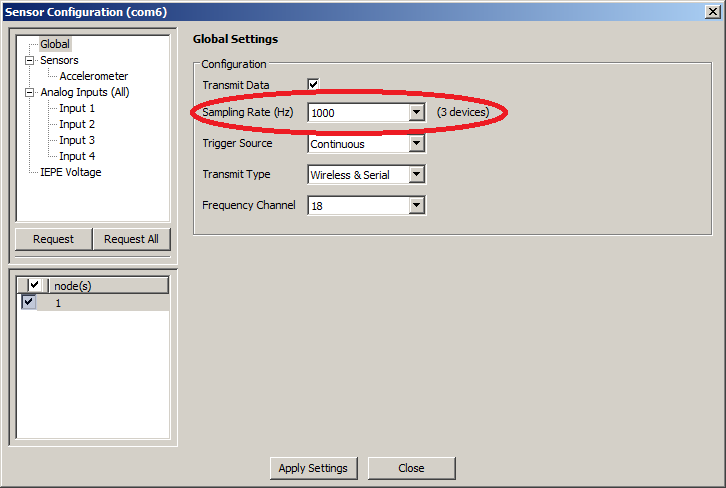
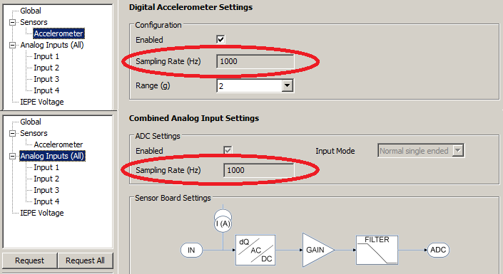
For the global network and nodes settings use the Inertia Studio tool (fig. 4.1). The tool also provides information about active nodes, their ID, battery status and signal strength. Please pay special attention to the global (fig. 4.2) and sensor (fig. 4.3) sampling frequency. For the correct function of the driver, all sampling frequencies need to be the same.
The highest processing and transmission rates are achieved when using sampling frequency 1000 Hz. For higher frequencies, the sampled values are merged into larger packets; however, these packets are sent with the frequency 1000 Hz. After processing the packet, the driver provides the last sampled (the newest) value. Other values from the packet remain unused.
For more information about wireless network or sensing nodes configuration, supported sensors and V-Mon 4000 parameters please see the V-Mon 4000 User Guide[4].
Chapter 5
Troubleshooting
In the case that the diagnostic tools of the REXYGEN system (e.g. REXYGEN Diagnostics) report unexpected or incorrect values of inputs, it is desirable to test the functionality outside the REXYGEN system using the Inertia Studio software. Also double check the configuration – the most common problems include:
- Hardware problem – incorrect wiring
- Communication port access problem – the communication port is used by other service
- Node ID in a From block is not listed in the .rio file (Invalid context)
- Signal alias in a From block is not valid (Invalid input mask)
- A From block was used for a multiple input (Range check error)
In the case that the given input or output works with other software tools and does not work in the REXYGEN system, report the problem to us, please. E-mail is preferred, reach us at support@rexygen.com. Please include the following information in your description to help us process your request as soon as possible:
- Identification of the REXYGEN system you are using. Simply export it to a file using the REXYGEN Diagnostics program (Target Licence Export).
- Short and accurate description of your problem.
- The configuration files of the REXYGEN system (.mdl files) reduced to the simplest case which still demonstrates the problematic behavior.
Bibliography
[1] Inertia Technology. V-Mon 4000. http://inertia-technology.com/v-mon-4000-series, 2014.
[2] REX Controls s.r.o.. Getting started with REXYGEN on Raspberry Pi, 2020. .
[3] REX Controls s.r.o.. Function blocks of REXYGEN – reference manual, 2020. .
Documentation reference number: 12481
2020 © REX Controls s.r.o., www.rexygen.com
